The FEP film has been in use for a long time for 3D printer vats and trays. Later nFEP appeared in the market as a better alternative to FEP. It promised faster print speeds and a longer life span of the film. But now there is new material on the street with the name ACF. The sellers are introducing it as having “almost no release force” or “long service life” while still having a decent light transmittance of 93 %. However, do the increased printing speeds outweigh the significant price increase? And do you really not lose any details by printing with a 300 µm thick film with a mate finish? Let’s compare results using ACF vs. nFEP vs. FEP films.
How did we test the chosen films at Ameralabs?
We decided to test five different vat films. The first material was FEP sheet with 50, 127, or 150 µm thicknesses. Then a single-thickness nFEP sheet with a thickness of 127 µm. Finally, an ACF sheet of 300 µm thickness.
To evaluate the results, we captured the light intensity, compared the peel force and layer surface area, compared the printing speed, and visually assessed the details of the prints.
We captured light irradiance spectra using an Ocean Optics ST-UV-25 spectrometer. The light source for the tests was Mars 4 DLP printer. To get accurate data, we recorded all measurements at the same position on the tempered glass of the printer by placing different films between the spectrometer probe and the printer’s glass. Which films resulted in the fastest printing?
We made 3D printing tests on an Asiga Max X43 DLP printer with AmeraLabs TGM-7 Grey resin. Accuracy is essential, so we filled the vat with 40 g of resin each time. Ameralabs town is excellent for evaluating printing quality, so we printed it as the printing specimen, placed it in the middle of the build plate, and sliced it with a layer height of 50 µm. The exposure we used was 0.276 s and 25 mW cm-2 light intensity. We kept all of the settings the same for all different films. We collected data on lift height and weight at separation detection from the log files of the printer. Lab conditions were at 23±1 °C and 40±10 % relative humidity.
We removed the AmeraLabs towns from the build plate after printing. They were washed in isopropanol for 10 minutes, dried for 15 minutes, and post-cured for 5 minutes.
Light intensity measurements of different films
First, before any printing starts, we must determine if any exposure adjustments are necessary due to different UV light absorption. All films were tested for UV light absorption using Mars 4 DLP printer as the light source. You can see the measurement data in the table below.

From the data, it is clear that with increasing FEP film thickness, more light is absorbed, increasing from -1.5 to -5.4 %. This change is probably not significant enough to be noticeable in terms of exposure. nFEP had marginally higher light absorption than identical thickness FEP sheet. Finally, ACF film had the highest light absorption of 7 %, which is no surprise since its thickness is at least two times higher than any other film. This measurement coincides with values given by the manufacturer.
To provide a perspective, if you were printing with 50 um FEP sheet at 2 s exposure and decided to switch to ACF, you would have to increase your exposure to 2.12 s. This small change could be noticeable in some cases, so if you had your exposure dialed in, you might need to increase your exposure slightly when switching to ACF.
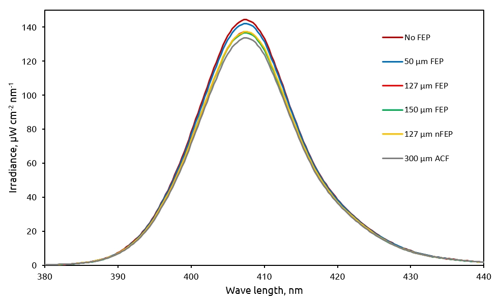
We also recorded the UV spectrum of the light that has passed through the different 3D printing films.
Here you can see a uniform reduction of irradiance throughout the emission spectrum of the printer. The curves of 127 µm FEP, 150 µm FEP, and 127 µm nFEP are indistinguishable from each other and overlap almost completely. That means that all films block light at different wavelengths similarly and there is no significant blocking of light with a specific wavelength. What is unrelated to this blog post but is very interesting is that the emission spectrum peak is 407.5 nm, even though the printer is advertised as 405 nm.
Comparing peel force vs. layer surface area
Asiga Max printers incorporate load cells into their designs, allowing them to detect print release from the film that coincides with sudden changes in load. The printer uses this data to stop moving the Z axis as soon as it detects the separation, saving much printing time. In the log files of the printer, it outputs the data of the maximum weight it measured and the distance the Z axis traveled before separation occurred for each layer which you can use to plot graphs and check the differences between the various 3D printing films.
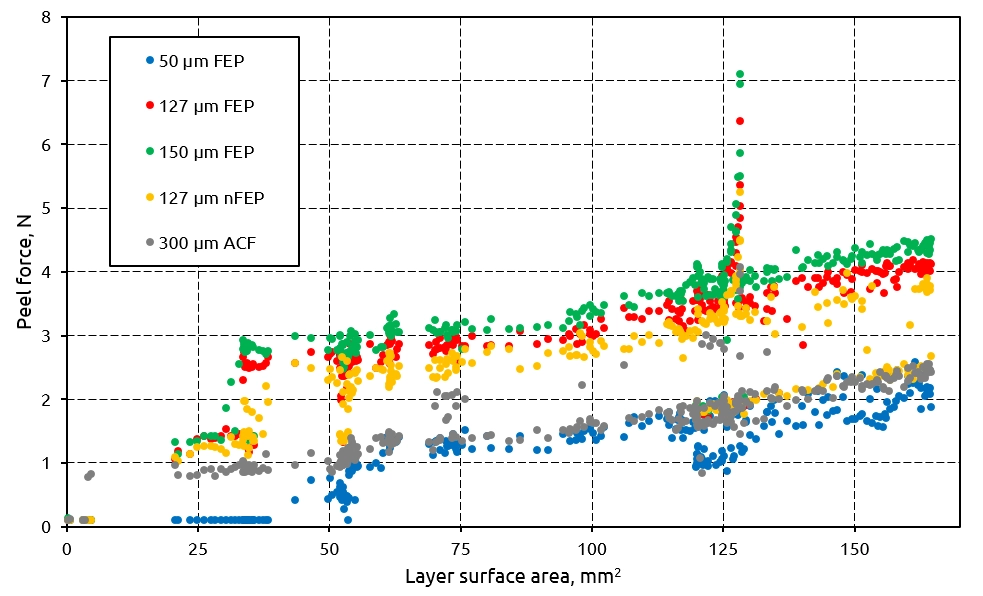
The peel force vs. layer surface area is in the picture below. As expected, the peel force increases when you print a larger surface area layer. A sharp increase of the peel force around 125 mm2 surface area is the data points of lower layers which means that the build plate was still submerged in the resin and close to the tempered glass, so it affected the separation. We observed the tendency that with increasing thickness of FEP sheets, the peel force also increases. The decrease of peel force between FEP and nFEP is small but noticeable. However, we achieved the lowest peel force from all tested films with 50 um FEP, with ACF film close behind.
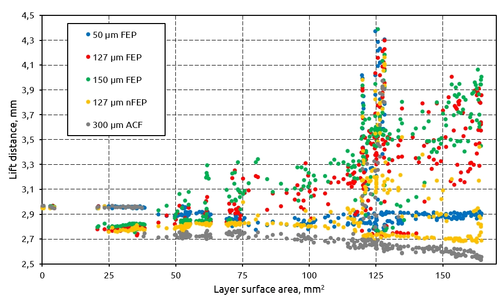
The correlation was not that direct when we applied the same procedure to the lift distance data. Even though you can see some increase in the lift distance with 127 and 150 µm FEP films, the rest of the tested films had a pretty consistent lift height, or even you can observe some decrease with ACF and nFEP. This could be due to how Asiga lifts the build plate and checks for separation, not necessarily because of the differences between the materials. Yet the overall trend of lift distance was lowest with ACF film, followed by nFEP and then 50 µm FEP. Here you can see layer surface area versus lift distance at separation for different 3D printing films.
Which films resulted in the fastest printing?
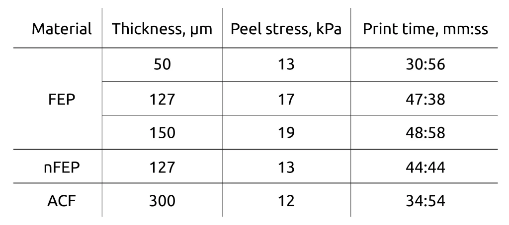
After printing the AmeraLabs town, we determined the print time by looking at the printer’s logs and checking each print’s start and finish times. You can look over the determined print times in the table below. Shockingly the fastest print was with 50 µm FEP film at 30 minutes and 56 seconds. It is probably due to how Asiga lifts the build plate. It has a setting called Separation Pressure limit, and since 50 µm FEP film had the lowest peel force of them all, it could lift the build plate faster than with other films.
Since most printers do not have this feature, we can expect that 50 µm FEP would perform differently in common printers. The second fastest print was with ACF film, which we could expect since that is the manufacturer’s claim. Just under 10 minutes slower than ACF was nFEP, and finally, the slowest prints were with thick FEP films.
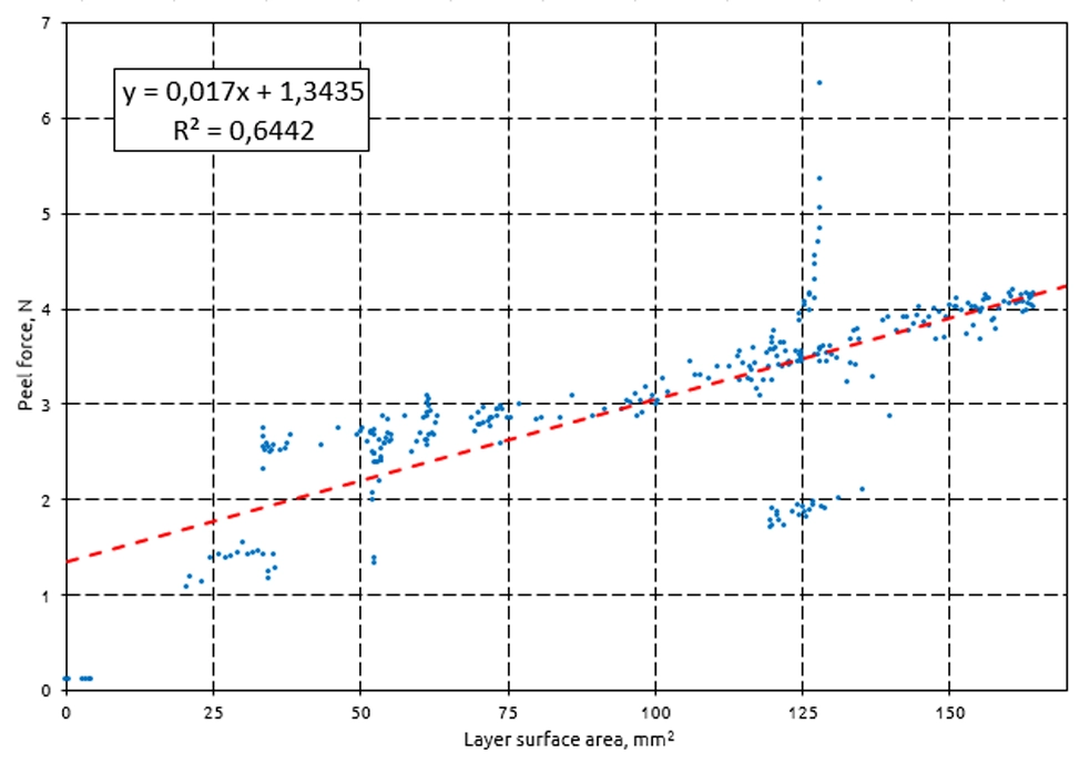
As we have seen in the previous chart, the higher the layer surface area, the higher the peel force. So we have then calculated how much peel forces are influenced by layer surface area for each type of film. We applied a linear fit to our layer surface area versus peel force data to do that. We calculated the slope of that line. The steeper the line, the higher the slope, and the quicker the peel force increases when the layer surface area increases. This slope is called peel stress. In the chart below, the coefficient of 0.017 would be that peel stress measured in pascals (Pa).
You can see the peel stresses for each film in the table below. The larger number, the larger increase in peel force. ACF had the lowest value of 12 kPa, then a small jump to 13 with 50 µm FEP and 127 µm nFEP, and the worst performers were 127 and 150 µm FEP. That means that with increasing surface area, the peel forces do not increase very fast on ACF film. In contrast, the peel force changes more quickly for the thickest FEP film. This also shows, that ACF might be a good choice if you are printing big solid models with very large layer surface areas.
Which 3D printing film produced best details?
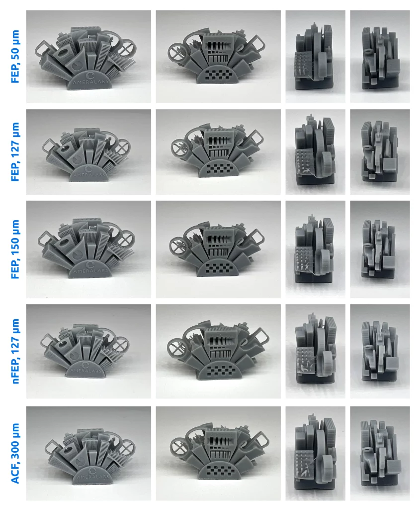
We evaluated the quality of the prints visually. The picture below shows the photos of the printed AmeraLabs towns using various 3D printing films. Overall, the towns were almost identical. The checkered pattern showed exposure to be good with all films. ACF had more vertical lines on the flat surfaces going all the way through the model. We printed two more AmeraLabs towns to ensure we get vertical lines when printing on ACF film. Those prints have proven that ACF prints have more vertical lines on the flat surfaces going through the model.
So is ACF an alternative worth considering?
Overall, ACF film fulfills its promises of faster printing speeds, lower peel force, and not that much greater UV light absorption while still retaining details on the printed parts. This should be especially beneficial when printing with printers that have bigger screen sizes and prints that have larger surface areas. However, the presence of visible vertical lines and the significant price increase could deter you from switching to it. Especially since 50 µm FEP performed very well in this short test which could be a good option for small printers and people who do not mind changing the film more often. The only thing that is very important and we didn’t test yet is the durability of the films. Hopefully, we will crowdsource from the feedback of the community. So if you have tried different 3D printing film materials, feel free to provide your insight.


